

FEA Background
The finite element analysis (FEA) method is used to model and approximate physical phenomenon through the use of partial differential equations. Engineers apply the finite element method (FEM) through using FEA computer software which provides critical insight into a design’s performance prior to physical testing.
Analysis Prior to FEA
Prior to FEA, engineers were limited to the use of hand calculations and physical testing. While these methods did an adequate job at ensuring designs met with performance requirements, they provided limited performance insight and often required the use of a guess, test, and revise approach to design. Hand calculations also limited the amount an engineer could optimize a design because complex designs were often too difficult to analyze by hand. With FEA we gain access to far more detailed information on a design’s performance.
FEA Benefits
- Analyze complex loading scenarios, environments, and designs.
- Improve design optimization through access to more performance information.
- Reduce the number of prototype iterations required prior to reaching an optimized solution.
- Gain a strong understanding of a design’s performance.
- Learn why
a design isn’t meeting with performance requirements. - Simulate critical qualification testing scenarios.
- Model the performance of materials within their plastic region.
- Solve non-linear analysis problems.
Hand Calculation Benefits
- No need for expensive software.
- Gives a good starting point for a design.
- Typically faster to
setup than a complex FEA model. - Adequate for the complete analysis of simpler problems.
Combining FEA and Hand Calculations
Engineers that use FEA should combine it with hand calculations. This provides the benefit of a good starting point for a design which can be further optimized with FEA. Hand calculations should also be used to validate FEA results to determine the accuracy of the model.
Gaining the benefit of FEA without the steep upfront cost
Due to the high cost of FEA software licenses and training, many engineering and product development companies decide not to invest in FEA capabilities. Instead, companies partner with engineering firms that have teams which specialize in FEA full time and therefore can afford the steep licensing costs and training.
Analysis & Optimization With Hand Calculations
To better understand how much an advantage FEA gives during the design process, it’s first necessary to understand how analysis and design optimization are performed without the use of FEA.

Without the use of FEA, geometries such as the above example need to be simplified when performing design calculations.
The example design would be simplified into a beam with two pinned supports and a cantilever end as shown below.

We would first calculate the moment and shear loads as well as the reactions using statics.
Moment Calculation

Reaction & Shear Calculation

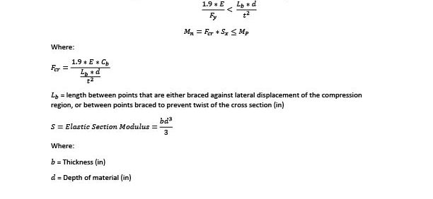
Design of Members for Flexure – Rectangular Bars
Once the loads have been determined, we need to calculate the capacity of the design cross-section. We start by determining the flexural capacity which typically controls for steel members in bending.
Source: AISC – 14 Sect F12 Page 16.1-63
Yielding – Check if yielding controls or if lateral-torsional buckling controls.

If yielding controls, then use the following equation to determine the flexural capacity.

Lateral-Torsional Buckling – for slender sections
a. For rectangular bars with the following bent about their major axis

b. For rectangular bars with the following bent about their major axis
A design factor of 1.67 (ASD) should be applied to the flexure design in accordance with the AISC. Design factors are used to account for differences between the calculation and real world. Depending upon how many assumptions are used during the design phase and how critical it is for a design to pass on the first iteration you may also want to add in a significant safety factor.
Optimize With a Spreadsheet
By using the above equations and design factor and plugging them into a spreadsheet you can then calculate the optimal depth for given thicknesses at different locations. This can be done quickly with using excel’s internal solver.

Once the depths have been determined, a CAD model can be generated. Use a curved shape that meets with the calculated depth requirements at each point. The curve shape prevents undesired stress concentrations from forming.
Check Other Design Limits
While flexure controls most steel designs, you will still need to check all other design limits such as bearing capacities, shear, serviceability, and more. Once all other design limits have been incorporated you will have arrived at a final design.
Manufacture a Test Prototype and Iterate
With the initial design finished, it’s time to manufacture it and test that it meets performance requirements. This starts the design iteration process which can take a significant amount of time, especially for more complex designs.
Limits of Hand Calculations
For handling more advanced analysis than the provided example, such as non-linear, complex geometries, or multiple simultaneous loading types FEA is typically required. However, for more advanced analysis scenarios hand calculations can still offer a good reference and starting point.
Optimization & Analysis With FEA
FEA can greatly improve the design process by providing detailed information on a design’s performance prior to prototyping. This information improves the design optimization process and cuts down on the number of high cost prototypes that are needed for testing.
Create a model of your product
The first step is to create a model of your product that accurately depicts the product’s performance for the given loading scenario but eliminates any unnecessary components which would complicated the analysis.
- The provided example was simplified by separating it into top and bottom sections.
- The shoes, screws, t-handle, and other non-essential components for the analysis were removed.
- Pin constraints were then placed where the pivot pin and nut ears were.
- The bearing load was then applied to where the clamp shoe was to simulate the clamping force.
- A mesh was then generated and refined which is used during the computational analysis.
- Finally, the simulation was run and a color contour stress plot was generated.


Post-Processing and Reading a Color Contour Plot
Contour plots give engineers a detailed understanding of how a design reacts to loading at every point in a system. This allows engineers to make data-driven design decisions with complex geometries, designs, and loading scenarios.
Each color of a contour plot indicates a stress value. For example in the above color contour plot, dark red indicates stress at or above 55
Model Validation
Prior to accepting your FEA results, you should first apply engineering judgment to the solution to determine whether or not it is reasonable. If the result seems reasonable and it’s possible for your problem then you should also run a hand calculation to validate your results. The final step in verifying your model is to build a testing prototype in order to validate your model against real-world results.
Optimization with FEA
Once the model has run properly and the results have been validated an engineer can start with optimization. An engineer then iterates through the following steps until an optimal solution is reached.
- Remove and add material in accordance with the FEA results to minimize material.
- While doing this it’s important to keep in mind manufacturing methods that will be used for the product in order to keep costs to a minimum.
- Run the analysis again with the new design.
- Determine whether to iterate again on the design or accept it as optimized.
Conclusion
FEA offers improved design optimization capability and access to performance information that would be otherwise unavailable. However, the high-cost of FEA software and training limits its availability as a tool to many.
Hand calculations can do an adequate job for designs where optimization isn’t needed and the design and loads are well understood. Hand calculations also offer a good starting point as well as the ability to quickly determine whether an idea can work prior to investing substantial time in creating a model.
In order to attain the benefits of a strong FEA model while not breaking your budget on licensing fees or spending a significant time learning a new complex software you can hire out FEA to experienced engineering consultants.


ASR is a mechancial engineering firm that specializes in advanced design and analysis. If you have a problem that can benefit from FEA or CFD then contact us today to speak to one of our experienced engineers or for a free quote.
Well written content like this restores my faith in quality writing. I finally found information I can agree on and use. Thank you for sharing.